Printed circuit boards are essential for computers, but how does a printed circuit board work? This guide shows the basics of PCBs.
Have you wondered what exactly goes into your phone or computer to make it work? A printed circuit board technology is what our whole modern world is based on.
Since they go into everything around us, you’re even worried about being hacked or spied on.
A PCB is like a black box to most people—they have no idea how it works, and they’re afraid to take a look under the hood.And it is different form PCBA.
We’re here to tell you it’s okay to look! As long as you don’t try to drill a hole in the board—keep reading to find out why.
Table of Contents
What Goes in and on a PCB?
First of all, we need to know what goes into it, right? A printed circuit board, or PCB, is a wafer of one or more of these materials:
- Woven and non-woven glass
- Resin
- Copper
- Cotton paper
- Matte glass
- PTFE (polytetrafluoroethylene)
- Ceramics
- Alumina
- Aluminum
- Polyamide
A long list, but necessary, since there are so many different kinds, such as rigid, flex, and rigid-flex circuit boards.
The different materials combine in different configurations to perform a design goal. This can be heat dissipation, fast and accurate transmission of electricity or any number of other requirements.
Some materials are more durable than others but cost-prohibitive. However, certain applications, such as military use, require high-end materials for the production of the PCB.
What Is a Printed Circuit Board?
A PCB is how our lives work today. It’s typically made of one to forty layers of substrate and copper foil “traces.” It’s similar to an electrical grid for a city, or even a street map.
We often imagine them going into only computers. But phones, TVs, cars, airplanes, clocks, and even your coffee pot is chock full of PCBs. If we continue to think of a PCB as a city, it’s how city hall talks to the fire department, and the central business district links to residential areas.
The different parts of a computer, for example, like the CPU, RAM, GPU, all need to communicate to work through different tasks. The PCB is what connects them in a tightly wound web of copper and fiberglass.
Everything is so close together in a PCB, which often causes complications. Thermal management and electromagnetic problems are the biggest issues PCBs face. Professionals call this Electromagnetic Interference or EMI.
Thermal management issues and EMI often cause early degradation of the board or of its ability to function.
For this reason, they use non-conductive materials in combination with copper in layers. The only layer you usually see is the top layer. If you drill into a board to fit it into a custom case, you could make it completely inoperable.
Because you don’t see traces doesn’t mean there aren’t any on lower layers.
How Do Circuit Boards Work?
Circuit boards use a host of “tools” to perform their designed tasks. These parts act in a similar way to stop lights, parking lots, roundabouts, and other traffic control systems.
These tools are:
- Capacitors
- Resistors
- Diodes
- Inductors
Capacitors store an electric charge and act as a sort of parking lot for electricity. Resistors do as they say and provide resistance in a system. Imagine a yield sign or flashing yellow, which acts to generally slow traffic and prevent overloading a road or causing a collision.
In a system without braking, some components of the PCB would overload with electricity or overheat as all the electrons try to enter it at once. That heat also contributes to the catastrophic degradation of the system, even damage.
Diodes are like one-way streets, and allow electricity to flow in only one direction once passing through it. That way electricity can’t surge backward and cause a see-saw motion of electrons. This creates magnetic waves and heat, which as we know are no good for the system.
Inductors can store electrical energy as a magnetic field. Also, they prevent AC electricity from flowing while still allowing DC electricity to pass through. This allows for the transformation of electrical states at the very least.
Putting It All Together
The components of the board (the chips) contain the transistors, which do the calculations. The PCB acts as the roadway network to those places, and connects the electrical currents, as well as protect them from overload.
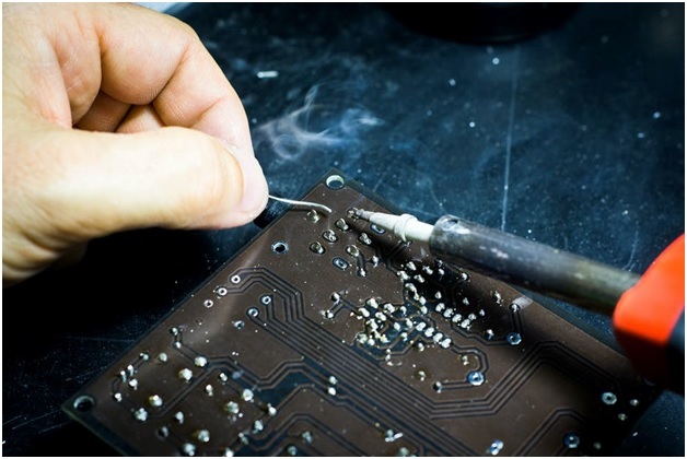
As components are set into the board and soldered on, they may contact only one layer. Or, they may contact many layers at different depths to reach components.
This complexity makes it difficult for humans to design by hand. Computers assist in the design by calculating best pathways for traces. This is called CAD or Computer Assisted Design.
Still, even with the help of computers failures happen. This blog posts can help you learn more about why even a good design on paper doesn’t translate into a practical one.
Although, if you’re a hobbyist who wants to break into making your own PCB, don’t be afraid. There are actually a few DIY processes for less complex systems.
This includes a “breadboard” circuit array usually used for testing. This provides a wonderful learning experience.
Closing the Circuit
Now that you know how a printed circuit board works, and what it can do, don’t you feel better? They’re everywhere around us, and essential for our way of life today.
Eventually, they’ll get smaller and more complex until a new technology replaces it. Just like the old method of manual tracing and exposed wires and vacuum tubes were replaced.
Then we’ll have a new black box to figure out, though for now we have what we have and we’re happy about it!
If this tech article tickled your transistor, we’ve got plenty more for you to read!